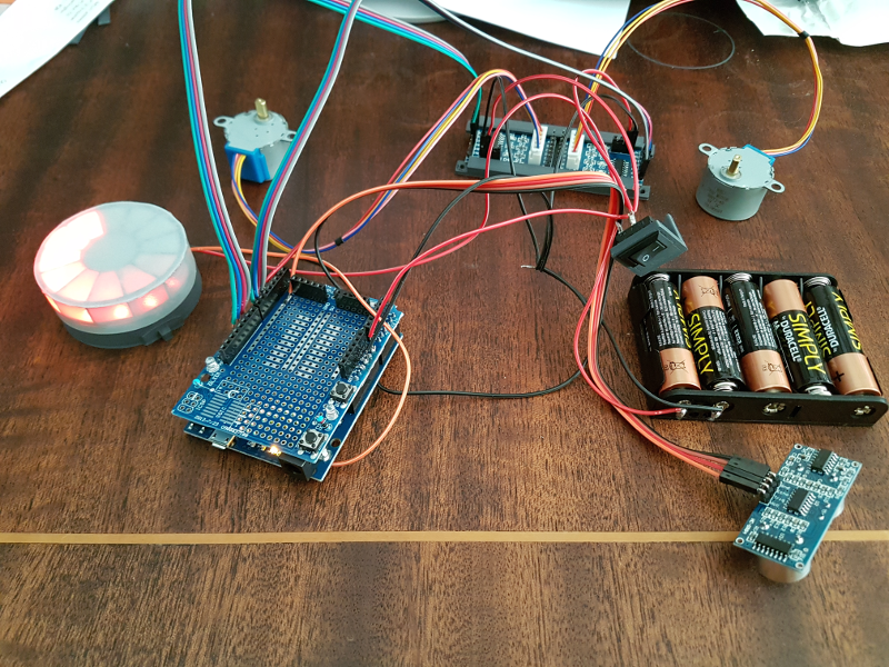
The other day I started my HullPixelBot journey (http://goparker.com/post/2018-05-25-plastic-parts-printed/) and I have made some progress since then.

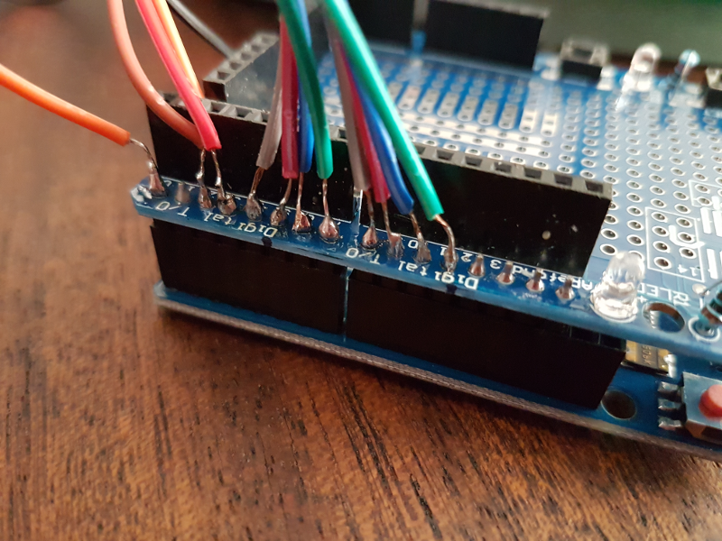
So I did a spot of soldering and wired everything together. That was a fairly straightforward process except that because I didn’t have any male type connectors (only female-female) it was a bit more fiddly than it needed to be as I was soldering directly on to pins on the Arduino board. To be precise, I was actually soldering on to the shield board as I just happened to have one and it has little pins exposed on the outside of the board.

This is not something that I particularly recommend as I am pretty sure that they will be more fragile connections than with proper connector. However, I was impatient to test that all the electronic parts were working.
An observation that I made that seems to be the case is that there is sufficient power from the USB connection to power everything. So whilst you are testing and deploying the programme code you can save your batteries.
With the PixelBot lying disembowelled until I can fully assemble it in its chassis, the fine tuning of the motor code was pretty boring. So I skipped it for now and raced on to put on a light show. It uses a 12 pixel rgb NeoPixel ring.
I installed the NeoPixel library (https://learn.adafruit.com/adafruit-neopixel-uberguide/arduino-library-installation) and started by deploying one of the example sketches. I picked the RGBWstrandtest because it had rgb in the name. I had to make sure that the data pin was set to the right one (zero in my case) and change the number of leds that it was expecting. And what a lovely light show it made. I was pleased because the pixel ring was obviously working. The next step was to start fiddling with the sample code to make sure that I understood what it was doing.
I started by trying to get a particular pixel to light up.
strip.setPixelColor(0, strip.Color(255, 0, 0));
Perfect. The pixel that I expected to be at index 0 (the first parameter of setPixelColor) lit up red (the colour that I expected from RGB(255, 0, 0), RGB(red, green, blue)). So let’s try the next pixel over by increasing the index by one.
strip.setPixelColor(1, strip.Color(255, 0, 0));
Wat? The next pixel over is lit up (Hooray!) but it is blue (Haroo…). Turns out it was a pretty simple mistake.
When you declare your NeoPixel strip (in my case it is a ring, but I haven’t renamed the variable yet) you specify the encoding that you will be using to communicate with the pixels.
Adafruit_NeoPixel strip = Adafruit_NeoPixel(12, PIN, NEO_GRBW + NEO_KHZ800);
This is the NEO_GRBW + NEO_KHZ800 bit above. The mistake is that that little bit of code that I inherited from the sample file that I chose with RGB in the name refers to a different kind of pixel that has a pure white component to it (the W bit of RGBW). So by simply removing the W from that declaration, it all worked as expected.
Adafruit_NeoPixel strip = Adafruit_NeoPixel(12, PIN, NEO_GRB + NEO_KHZ800);
Now on to greater things. I was armed with the ability to light pixels so I wanted to come up with a custom animation (i.e. one that was different from the sample code). The effect that I went for (that should be shown in the animated gif at the top of the page) was to have a leading pixel whizzing around the ring with a trail of faded pixels behind.
In order to achieve this I needed to be able to set an individual pixel’s brightness. When you set the colour of a pixel you give it an RGB value where each of the Red, Green, and Blue parts can take a value between 0 and 255. A value of zero is completely off and 255 is completely on. The combination of the different intensities of the three colours allows you to create lots of different shades.
Knowing that, we can make a method that can scale the RGB components to adjust the brightness. By multiplying each of the RGB components by our brightness parameter and dividing it by the maximum brightness (255) we can change the brightness of the colour without changing its shade.
uint32_t adjustColourBrightness(uint8_t r, uint8_t g, uint8_t b, uint16_t brightness)
{
  uint8_t newRed = brightness * r / 255;
  uint8_t newGreen = brightness * g / 255;
  uint8_t newBlue = brightness * b / 255;
  uint32_t newColour = strip.Color(r, g, b);
  return newColour;
}
I also wanted a way to do the same, but for a ‘merged’ colour like the one that is returned by the strip.Color method which returns a uint32_t value. In order to do this it is necessary to split the merged colour in to its RGB components. That requires a bit shift.
// mergedColour is a uint32_t
uint8_t r = mergedColour >> 16;
uint8_t g = mergedColour >> 8;
uint8_t b = mergedColour;
Note that the component parts are a uint8_t which is an 8 bit unsigned integer. This is important as when you try and put the 32 bit unsigned integer in to it it will chop off the remaining bits that don’t fit.
The bit shift (done using the » operator) will shift all the bits of the variable to the right by the number of spaces that you specify.
For an example consider the colour red, which is RGB (255, 0, 0). For the red component, 255, in binary would be 11111111, that is 8 bits all set to 1. Each of the other colours would be set to zero, or 00000000. If you put them all together you would get 111111110000000000000000. Actually you would get 00000000111111110000000000000000 because we are storing it in a 32 bit integer.
So, to get the individual components back we do the following. For red, right shift by 16 bits and cram it in the 8 bit integer. 00000000000000000000000011111111 following the shift and then chop off all but the last 8 bits to get 11111111 which was the red that we started with. For green, right shift by 8 bits. 00000000000000001111111100000000 gives us 00000000 once we have cropped down to the last 8 bits. Finally blue doesn’t require any shifting as it is already contained in the last 8 bits. So 00000000111111110000000000000000 becomes 00000000.
In order to make the tail animation work I need to be able to turn all of the pixels off. In order to make it a bit more flexible I did this by making a method that turns all the pixels ‘on’ to a particular colour.
void turnAllOn(uint32_t colour, uint8_t wait)
{
  for(uint16_t i=0; i<strip.numPixels(); i++)
  {
    strip.setPixelColor(i, colour);
  }
  strip.show();
  delay(wait);
}
I can then call this with the colour black (all off).
void turnAllOff(uint8_t wait)
{
  turnAllOn(strip.Color(0, 0, 0), wait);
}
The reason that I need this for the tail effect is that all of the pixels that are not part of the tail should be turned off.
And finally we have the method showTail itself. It initialises a brightness value to full brightness. This is what will be used for the first pixel. Then for every pixel after it, reduce the brightness by half. The other important method being called is the correctIndex method that just makes sure that the ledIndex being generated remains in range and ‘wraps’ around to complete the loop of the pixel ring.
int16_t currentIndex = 0;
uint16_t tailLength = 12;

void showTail(uint32_t colour, uint8_t wait)
{
  uint16_t brightness = 255;

  for(uint16_t i=0; i<tailLength; i++)
  {
    int16_t ledIndex = currentIndex - i;
    ledIndex = correctIndex(ledIndex);
    brightness = brightness / 2;
    uint32_t newColour = adjustColourBrightness(colour, brightness);
    strip.setPixelColor(ledIndex, newColour);
  }
  strip.show();
  delay(wait);
}

void loop()
{
  turnAllOff(0);
  showTail(strip.Color(255, 0, 0), 100);
  currentIndex = currentIndex + 1;
  currentIndex = correctIndex(currentIndex);
}
I am looking forward to assembling the PixelBot next. I ought to give it a name. I will think of something.
No comment
Say something
Thank you
Your post has been submitted and will be published once it has been approved.
OK
OOPS!
Your post has not been submitted. Please return to the page and try again. Thank You!
OK