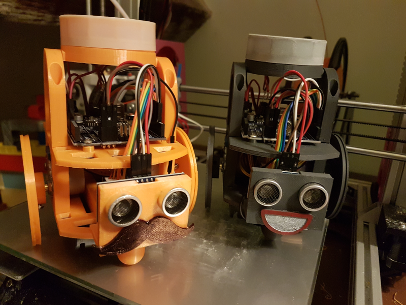
Introducing Butch. Butch is Smiler’s new stable mate. Look how happy she is to have some company!
I thought that it would be quite neat to introduce my son to some of this, particularly to the Logo turtle-esque control programming coming from Rob’s HullOS.
Obviously, I don’t want him playing with my toy so I had to build another one. Hence, Butch.
Butch has had some fairly extensive modifications to the base chassis design which I devised based on my experience of the stock design that Smiler uses (apart from her winning smile). I modified the base plate so that the stepper motor driver board sled, that I designed for Smiler to accomodate her mounting holes, was integrated in to the chassis plate. I also included screw holes in the top of the sled so that it is still possible to mount the original board types that Rob was using.
In order to reduce the number of screws needed I also redesigned the distance sensor mount and the switch holder to incorporate ‘bumpers’ that block the ends of the sled and seal in the driver boards without needing extra screws.
Finally, I also punched a load of holes in the design as it isn’t necessary for the plates to be one solid piece and it saves on plastic. This also has the advantage that it makes routing the various cables a lot easier.

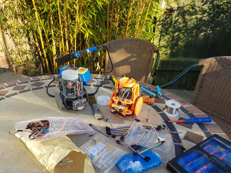
I eventually got around to doing all the soldering, and as it was such a nice evening I decided to do it in the open air in my garden. This was quite pleasant.
I did have a slightly annoying experience. After I had finished all the soldering and wiring I went to flash it with the control code and it wouldn’t even register when I plugged in the usb. I started off concerned that I had never tested the Arduino Uno board before doing all the soldering, so I had no idea if I had done something or the board has arrived faulty or something. I started yanking out the cables, not in a very scientific or methodical way, and all of a sudden lights appeared on the board! It wasn’t dead.
So I flashed the board with my simple turn the robot and light the lights program and started plugging all the cables back in. This time I was a little more careful about approaching this systematically and I discovered that everything stopped working when I connected the power to the rear stepper motor driver (another component that I hadn’t pre-tested). I established that it didn’t matter what 5v or ground sockets I plugged it in to, thus isolating the problem to the board.
So what could that be? At this point I vaguely remember that when I was assembling all of the non electronics parts I thought “I wonder if this thing could be a problem”. Then in lazy fashion I thought “nah, proceed”.
It turns out that it really was a problem, and this was it. The mounting holes for the battery compartment, which are underneath the bottom chassis plate, are directly beneath the stepper driver boards. This meant that when I screwed my quite long screws up through the base they connected with the underside of the driver boards and were obviously shorting something out. When I removed the screw, everything worked. So I sawed off the end of those screws, put it all back together, and now we are in business!
No comment
Say something
Thank you
Your post has been submitted and will be published once it has been approved.
OK
OOPS!
Your post has not been submitted. Please return to the page and try again. Thank You!
OK