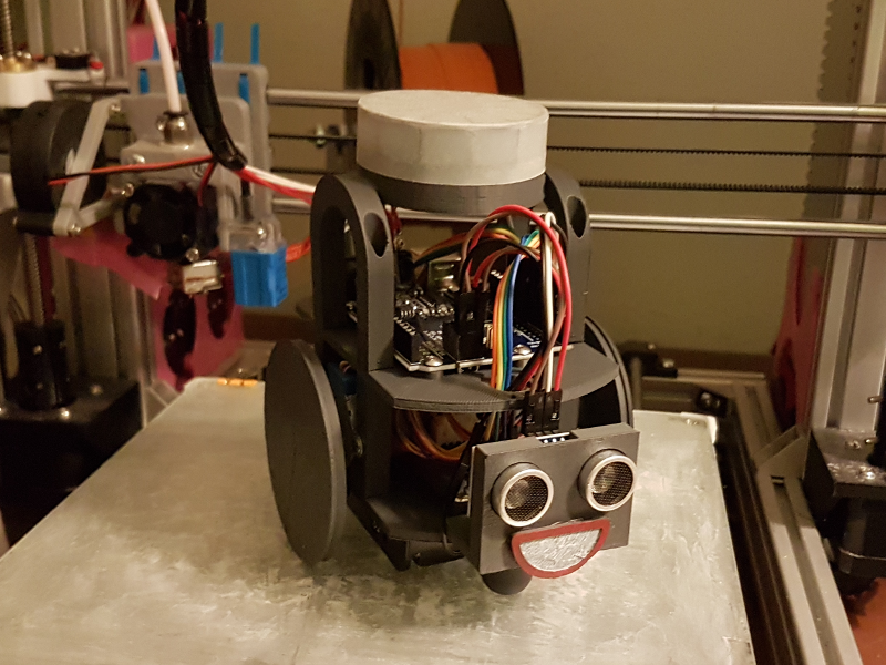
Smiler has been revived and she is now better than ever following the Dead Led debacle (http://goparker.com/post/2018-05-29-dead_led/)
The replacement LED ring and the necessary resistors and capacitors necessary to properly protect it all arrived. At the same time I also ordered a bunch of different connector cables so that I could make a neater job of the wiring and also make it more easily modifiable. In the previous incarnation I only had female-female connectors and so I invariably ended up cutting the connectors off and soldering directly to the prototyping shield that I had. This was fine and functional, but had the disadvantage that I couldn’t easily change it around without resorting to getting the soldering iron out.
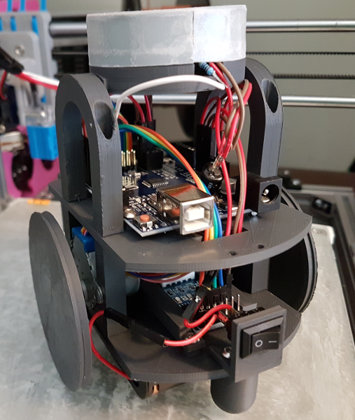
The photo below shows the backend view. I think that this is a much neater arrangement and it also does away with the shield board altogether as it is no longer necessary and was comparitively bulky.

Another difference from the earlier posts is that my Arduino Uno board arrived. It had taken a circuitous route (did you see what I did there?) due to a mailing mishap. This replaces the Leonardo board that was a spare that I had borrowed from the Troublesome Tanks project (more on that another time) to satisfy my impatience for getting started.
At around the time the Uno board arrived I discovered why I should be particularly pleased that it had. I wanted to have a little play around with Rob’s HullOS (https://github.com/HullPixelbot/HullOS) which is his Arduino controller code for the PixelBots that allows them to accept a higher level language to make them do stuff. Turns out that HullOS is too big for the Leonardo board memory available, but fits the Uno.

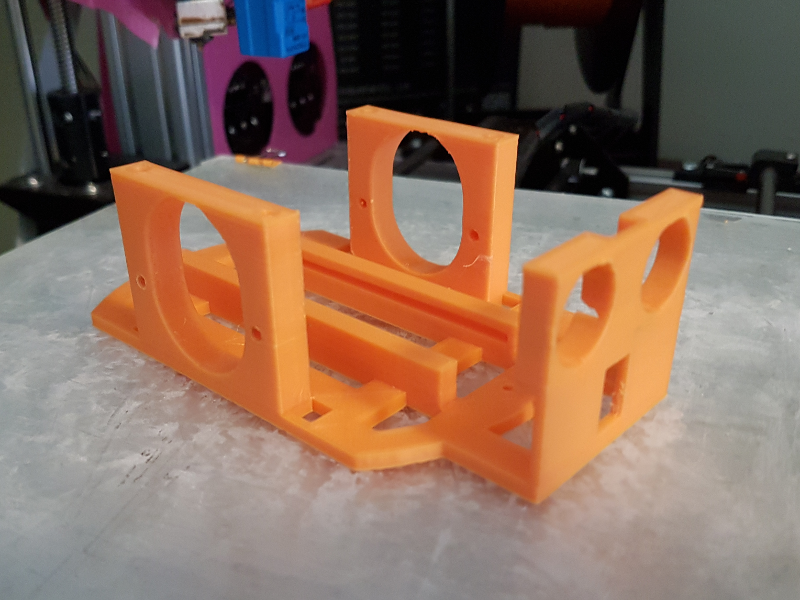
I have also explored some further chassis remix ideas fuelled by my stepper driver sled design. I was wondering if it was possible and/or practical to merge parts of the chassis in to one piece to reduce the number of bolts necessary to assemble it. The picture above is what I came up with. I would say that it came out ok, but there appear to be valid reasons for not doing this.
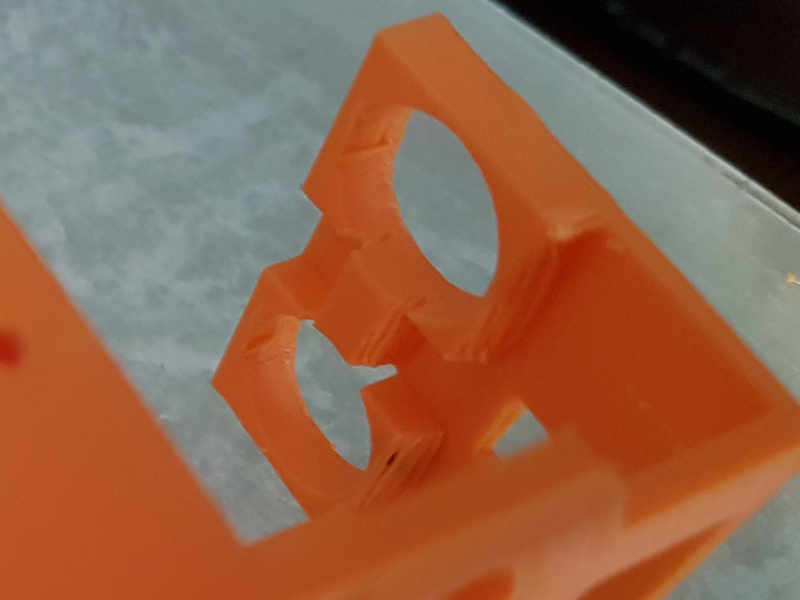
In the original design, the two motor holders and the distance sensor holder are printed separately. This means that they can be printed on their sides resulting (more or less) in no overhang. This results in a much cleaner print (of those parts) as the overhang can result in some droopage of the filament due to gravity. This is particularly noticable on the overhang on the distance sensor holder as shown in the photo below.

To a certain extent, this can be mitigated by the design - such as if the overhang size is reduced or faded in (with an arch for example).
I also incorporated the switch location in the ‘face’ of the distance sensor holder as I thought that it looked a bit like a nose. When I put it all together, I ultimately decided that it didn’t look as cute as Smiler’s smile so the prototype chassis is currently soulless.
I do like the way the stepper motor driver sled rails are incorporated in to the base so I will probably evolve the design a little to separate out the parts again so that the base (with integrated rails) can be used in place of the standard design.
No comment
Say something
Thank you
Your post has been submitted and will be published once it has been approved.
OK
OOPS!
Your post has not been submitted. Please return to the page and try again. Thank You!
OK